ASUS ROG Crosshair X870E Hero Motherboard Review
Author: Dennis GarciaBoard Layout and Features
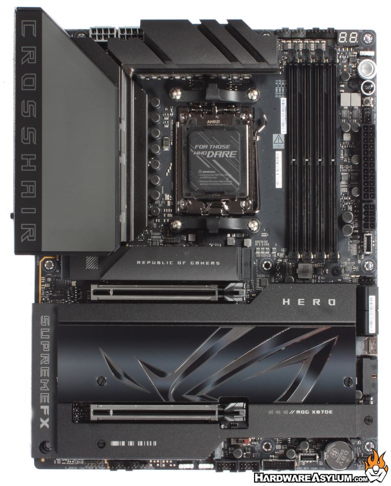
One thing that has always concerned me with motherboard design is how elaborate the various heatsinks have become and yet the board designs themselves have gotten to be quite simple. It is a bit of a role reversal but meshes well with modern builds.
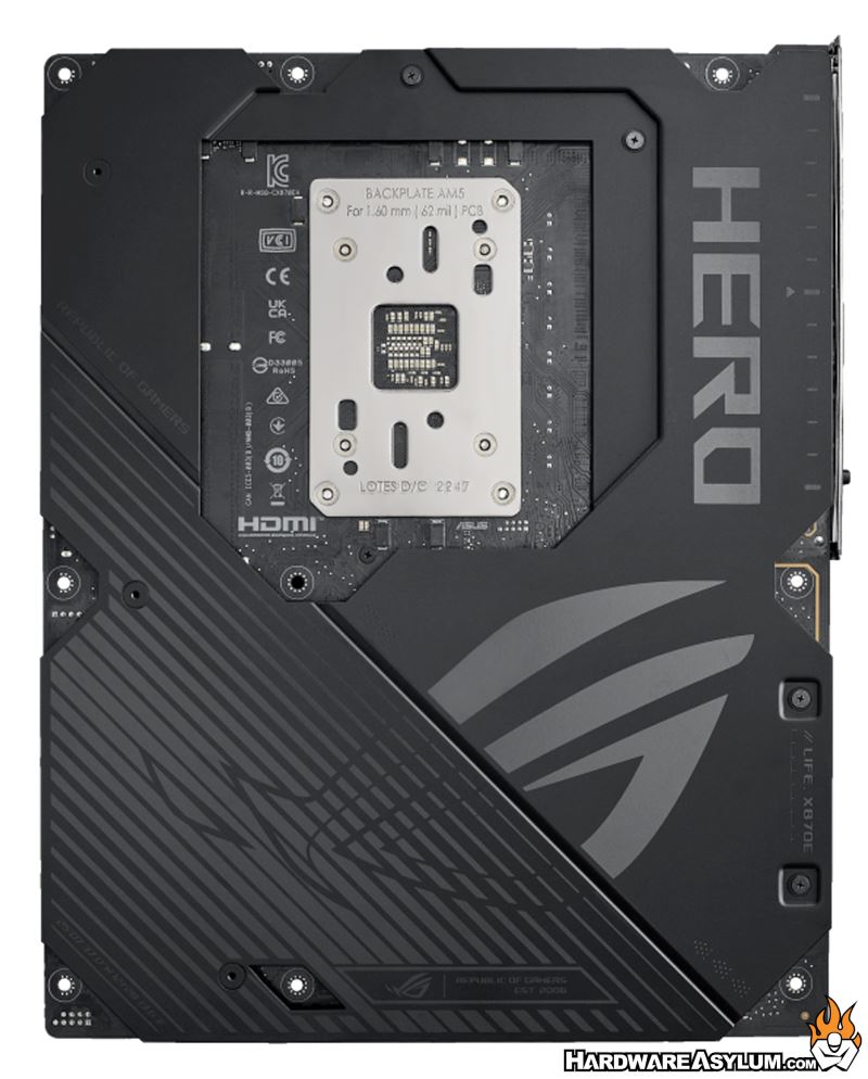
Flipping the board around you’ll find a full coverage backplate that not only reinforces the motherboard PCB but offers a little more protection and thermal capacity when drawing heat away from the VRM.
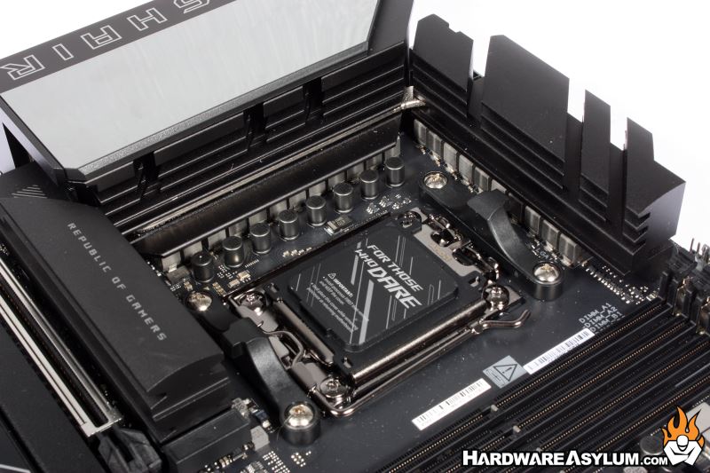
Unlike the Intel socket the CPU reinforcement plate is quite large and has solid metal connections for the retention bracket and for the heatsink. Of course, this is something that has been with AMD sockets since the Athlon 754 days and quite valuable when it comes to ensuring a solid heatsink to CPU connection.
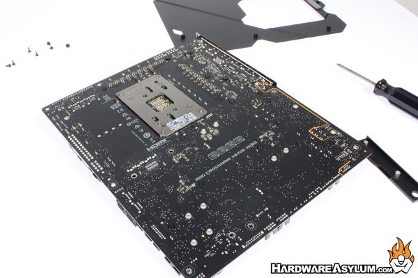
I did take it upon myself to remove the backplate, not only to see the PCB but, to prep the board for some later activities in this review. The thing you will notice right away is that there are hardly any through hole components on this board. Sure, you get the power connector, SATA and some VRM parts but, the PCI Express and memory slots appear to terminate elsewhere on the PCB.
Speaking of memory, the area under the memory slots is completely devoid of components and looks to be back drilled similar to what Gigabyte was doing with their previous generation of motherboard. Removing these “antennae” from the memory socket goes a long way to reduce EMI and ensure that high speed memory can remain stable at speed.
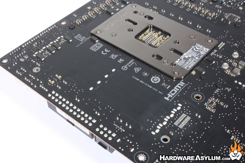
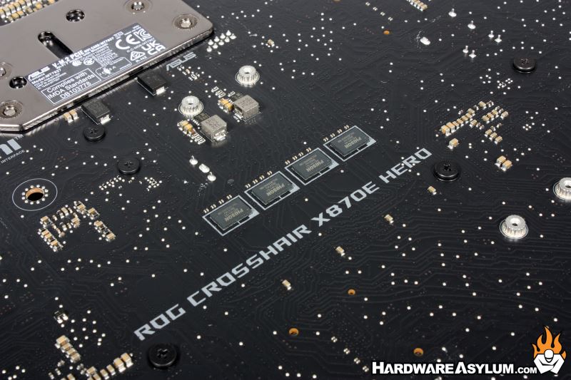
Something that we will start to see more of are the addition of redriver ICs to our PCI Express 5.0 enabled motherboards and devices. These little two channel devices help to condition the PCIe signal paths to ensure error-free data transfers without impacting data speeds.
The VRM found on the Crosshair X870e Hero is not for the faint of heart. There are a total of 22 power phases shown around the CPU socket which match the 18+2+2 teamed power solution supporting up to 110A of power delivery. The first 18 are dedicated to the CPU, with an additional 2 allocated to SoC and two extras for “Misc” or likely memory and other systems on the board.
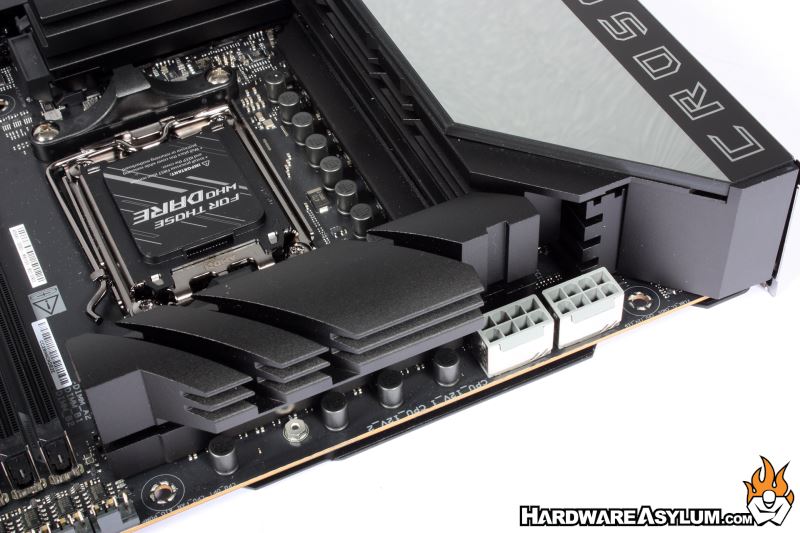
You will find two 8-pin CPU power connectors located in the upper left of the PCB with a special cut out in the heatsink allowing easy access to connect and remove the cables. It should also be noted that these connectors are the only grey ones on the board and are metal reinforced for added strength.