Gigabyte G1-Killer Sniper 2 Motherboard Review
Author: Dennis Garcia
Published: Sunday, August 21, 2011
Board Layout and Features Cont.
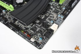
Internal SATA connections number seven. The black connections are SATA3 spec while the white connections follow the new SATA6 connection standard direct from the Z68 chipset. The remaining grey SATA ports are SATA6 compliant and are provided by the onboard Gigabyte branded controller.
The front panel connector is located in the traditional spot at the bottom of the motherboard. In the same vicinity you'll also find a "true" USB 3.0 header along with standard USB 2.0 ports. The dual BIOS chips are located near the chipset heatsink and feature white identification dots. These chips are not removable but given the nature of the dual BIOS recovery system you should never need to replace them.
For those of you who are worried about security Gigabyte included a TPM module header to handle your encryption needs. In case you didn't know this is what BitLocker uses to encrypt your hard drive.
For those of you who are worried about security Gigabyte included a TPM module header to handle your encryption needs. In case you didn't know this is what BitLocker uses to encrypt your hard drive.
The I/O panel features many common connections including PS/2 Keyboard and Mouse ports, digital audio over optical, USB2, USB3, eSATA, RJ-45 network connection, and five analog audio connections for 7.1 channel sound. A new feature of the Z68 chipset is the ability to use the built in GPU found in the LGA1155 processors. The HDMI Port found here is fully supported and can be used in conjunction with one or more discrete graphics cards of your choosing. The last feature on the I/O panel is located between the PS/2 and HDMI Ports and is amply labeled O.C. Pressing this button will automatically and instantly overclock your system. No more fiddling in the BIOS or loading desktop overclocking software, simply press and go.
G1 Killer Features Revealed
Creative CS20K2 Digital Audio Processor. The 20K2 DAP chip accelerates OpenAL 3D audio, X-Fi CMSS-3D, X-Fi Crystalizer and other advanced X-Fi audio processing. Unlike other audio processors this Creative chip uses a single PCI Express lane for communication and features an embedded RISC processor to safeguard against control latencies introduced by PCI Express. The 20K2 is a true processing unit that expands the audio I/O capabilities and features a DDR memory interface for increased local memory bandwidth.
All of these features can be seen in the photo above. The APU is located in the lower right next to the DDR memory chip. The caps used for the audio controller are not the typical Japanese design we have come to expect but rather Nichicon MUSE capacitors commonly found in high-end audio hardware.
To help reduce EMI leakage the entire capacitor grouping is shielded from the surrounding components.
Bigfoot Networks E2100 Killer NPU. The E2100 game networking platform is an embedded version of Killer 2100 Gaming Network Card. The NPU is designed to deliver maximum networking performance for online games by automatically detecting and accelerating game traffic ahead of other network traffic. The result is smoother game performance and less overhead since all network calls are handled by the E2100.
Visually the Killer E2100 isn't as complex as the Creative system but does encompass all of the components surrounding the NPU including the Marvell PHY chip at the top of the photo.
Visually the Killer E2100 isn't as complex as the Creative system but does encompass all of the components surrounding the NPU including the Marvell PHY chip at the top of the photo.


